4. Traditional modeling, the CSG way
CSG stands for Constructive Solid Geometry and describes the most basic way to work with solid 3D geometry, which is creating complex objects by adding and removing pieces to/from solids by using Boolean operations such as union, subtraction or intersection.
As we saw earlier in this manual, 3D-CAD-X can handle many types of geometry, but the preferred and most useful type for the kind of 3D objects that we want to design with 3D-CAD-X, that is, real-world objects, is, without a doubt, solid, BREP geometry, that is mainly handled by the Part Workbench. Unlike polygon meshes, which are made only of points and triangles, BREP objects have their faces defined by mathematical curves, which permits absolute precision, no matter the scale.
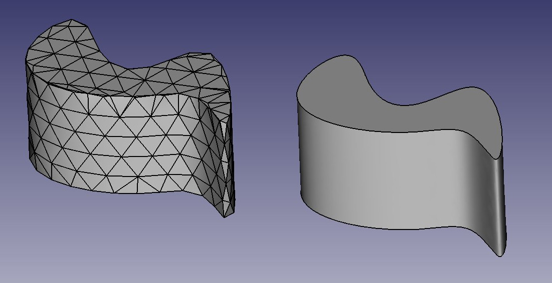
The difference between the two can be compared to the difference between bitmap and vector images. As with bitmap images, polygon meshes have their curved surfaces divided into a series of points. If you look at it closely, or print it very large, you will see not a curved but a faceted surface. In both vector images and BREP data, the position of any point on a curve is not stored in the geometry but calculated on the fly, with exact precision.
In 3D-CAD-X, all BREP-based geometry is handled by another piece of open source software, OpenCasCade. The main interface between 3D-CAD-X and the OpenCasCade kernel is the Part Workbench. Most other workbenches build their functionality on top of the Part Workbench.
Although other workbenches often offer more advanced tools to build and manipulate geometry, since they all actually manipulate Part objects, it is very useful to know how these objects work internally, and be able to use the Part tools since, being more simple, they can very often help you to work around problems that the more intelligent tools fail to solve properly.
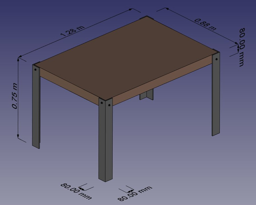
To illustrate the working of the Part Workbench, we will model this table, using only CSG operations (except the screws, for which we will use one of the addons, and the dimensions, which will see in the next chapter):
Let's create a new document ( Ctrl+N or menu File → New Document) to hold our table design. The document is initially called "unnamed" in the Model tab in the Combo View panel, but if you save the document ( Ctrl+Shift+S or menu File → Save As) as a new 3D-CAD-X document called "table.FCStd" the document will be renamed "table", which more clearly identifies the project.
Now we can switch to the Part Workbench and start to create our first table leg.
* Press the Part
 Cube button
* Select the Cube, then set the following properties (in the Data tab)
Length: 80mm (or 8cm, or 0.8m, 3D-CAD-X works in any unit)
Width: 80mm
Width: 80mm
* Duplicate the Cube by pressing Ctrl+C then Ctrl+V (or menu Edit → Copy and Paste) (No change will be evident, as the second object is overlaying the first.)
* Select the new object named Cube001 that has been created (Click on Cube001 in the left side Model tab)
* Change its position by editing its Placement property:
Position x: 8mm
Position y: 8mm
You should obtain two high cubes, one 8mm apart from the other:
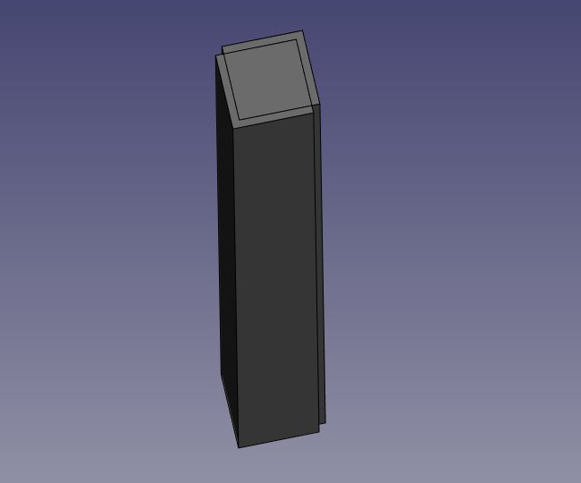
Now we can subtract one from the other: Select the first one, that is, the one that will stay, then, with the CTRL key pressed, select the other one, that will be subtracted (the order is important) and press the Part  Cut button:
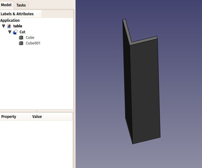
Observe that the newly created object, called "Cut", still contains the two cubes we used as operands. In fact, the two cubes are still there in the document, they have merely been hidden and grouped under the Cut object in the tree view. You can still select them by expanding the arrow next to the Cut object, and, if you wish, turn them visible again by right-clicking them or change any of their properties.
You can use Cut -tool and other Boolean tools also through "Combo view" with Part Boolean.svg Boolean. It gives more explicit but longer way to do it.
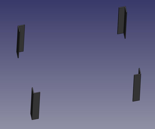
Now let's create the three other feet by duplicating our base cube 6 other times. Since it is still copied, you can simply paste (Ctrl+V) 6 times. Change their position as follows:
Cube002: x: 0, y: 80cm
Cube003: x: 8mm, y: 79.2cm
Cube004: x: 120cm, y: 0
Cube005: x: 119.2cm, y: 8mm
Cube006: x: 120cm, y: 80cm
Cube007: x: 119.2cm, y: 79.2cm
Now let's do the three other cuts, selecting first the "host" cube then the cube to be cut off. We now have four Cut objects:
You will notice that the cylinders are a bit longer than needed. This is because, as in all solid-based 3D applications, boolean operations in 3D-CAD-X are sometimes oversensitive to face-on-face situations and might fail. By doing this, we put ourselves on the safe side.
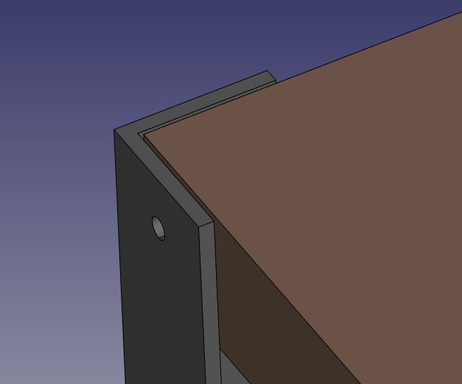
Now let's do the subtractions. Select the first foot, then, with CTRL pressed, select one of the tubes that crosses it, press the Cut button. The hole will be done, and the tube hidden. Find it in the tree view by expanding the pierced foot.
Select another foot pierced by this hidden tube, then repeat the operation, this time Ctrl+ selecting the tube in the tree view, as it is hidden in the 3D view (you can also make it visible again and select it in the 3D view). Repeat this for the other feet until each of them has its two holes:
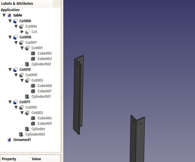
As you can see, each foot has become a quite long series of operations. All this stays parametric, and you can go change any parameter of any of the older operations anytime. In 3D-CAD-X, we often refer to this pile as "modeling history", since it in fact carries all the history of the operations you did.
Another particularity of 3D-CAD-X is that the concept of 3D object and the concept of 3D operation tend to blend into one same thing. The Cut is at the same time an operation, and the 3D object resulting from this operation. In 3D-CAD-X this is called a "feature", rather than object or operation.
Now let's do the tabletop, it will be a simple block of wood, let's do it with another Box with length: 126cm, width: 86cm, height: 8cm, position: x: 10mm, y: 10mm, z, 67cm. In the View tab, you can give it a nice brownish, wood-like color by changing its Shape Color property: